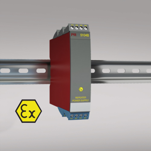
Features
- 1- or 2-channel version
- 3- / 5-port 3.75 kVAC galvanic isolation
- Loop supply > 17.1 V in hazardous area
- 20 programmable measurement ranges
- Universal supply by AC or DC
Application
- Supply voltage and safety barrier for 2-wire transmitters mounted in a hazardous area.
- Safety barrier for analog current / voltage signals from a hazardous area.
- 1 : 1 or signal conversion of analog current / voltage signals.
Technical characteristics
- The 20 factory-calibrated measurement ranges in the PR 5104B can be selected by the internal DIP-switches without the need for recalibration. Special measurement ranges can be delivered.
- PR 5104B is based on microprocessor technology for gain and offset. The analog signal is transmitted at a response time of less than 25 ms.
- Inputs, outputs, and supply are floating and galvanically separated.
- The output can be connected either as an active current / voltage transmitter or as a 2-wire transmitter.
Mounting / Installation
- Mounted vertically or horizontally on a DIN rail. By way of the 2-channel version up to 84 channels per meter can be mounted.
-
NB:
5104B is recommended as I.S. barrier for PR 5331D, PR 5333D, PR 5334B, PR 5343B,
PR 6331B, PR 6333B, and PR 6334B.
Please contact the sales for details.
Specification
Environmental Conditions
Operating temperature -20°C to +60°C
Calibration temperature 20...28°C
Relative humidity < 95% RH (non-cond.)
Protection degree IP20
Mechanical specifications
Dimensions (HxWxD) 109 x 23.5 x 130 mm
DIN rail type DIN 46277
Weight approx. 225 g
Wire size 1 x 2.5 mm2 stranded wire
Screw terminal torque 0.5 Nm
Vibration IEC 60068-2-6
2...13.2 Hz ±1 mm
13.2...100 Hz ±0.7 g
Common specifications
Supply
Supply voltage, universal 21.6...253 VAC, 50...60 Hz or 19.2...300 VDC
Fuse 400 mA SB / 250 VAC
Max. required power ≤ 3 W (2 channels)
Internal power dissipation ≤ 2 W (2 channels)
Isolation voltage
Isolation voltage, test / working 3.75 kVAC / 250 VAC
PELV/SELV IEC 61140
Auxiliary supplies
2-wire supply (pin 44...42 and 54...52) 28...17.1 VDC / 0...20 mA
Response time
Response time (0...90%, 100...10%) < 25 ms
Signal / noise ratio Min. 60 dB (0...100 kHz)
Accuracy Better than 0.1% of sel. range
EMC immunity influence < ±0.5% of span
Extended EMC immunity: NAMUR NE21, A criterion, burst < ±1% of span
Input specifications
Common input specifications
Max. offset 20% of max. value
Current input
Measurement range 0...20 mA
Min. measurement range (span) 16 mA
Input resistance Nom. 10 Ω + PTC 10 Ω
Voltage input
Measurement range 0...10 VDC
Min. measurement range (span) 8 VDC
Input resistance > 2 MΩ
Output specifications
Current output
Signal range 0...20 mA
Min. signal range 16 mA
Load (@ current output) ≤ 600 Ω
Load stability ≤ 0.01% of span / 100 Ω
Current limit ≤ 28 mA
Passive 2-wire mA output
Effect of external 2-wire supply voltage variation < 0.005% of span / V
Voltage output
Signal range 0...1 VDC / 0...10 VDC
Min. signal range 0.8 VDC / 8 VDC
Load (@ voltage output) ≥ 500 kΩ
External loop supply 29 VDC
of span = of the presently selected range
Download
Note : Design and specifications are subject to change without notice.
Note : Please make sure the product and the device which connect with RS-485 are on common ground, avoid damaged product.

